Industry
 Num:70
 See:2037
2021-05
27
Flyback type, forward type, push pull type, half bridge type, full bridge switching power supply advantages and disadvantages!
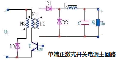
Single terminal forward excitation
Single-ended: Pulse transformer driven in one direction by a switching device.
Forward excitation: the primary/secondary phase relation of the pulse transformer to ensure that the secondary side of the transformer supplies power to the load when the switch is on and the primary side of the pulse transformer is driven.

The biggest problem of this circuit is that the switch tube T works alternately in the on/off two states. When the switch tube is turned off, the pulse transformer is in the "no-load" state, in which the stored magnetic energy will be accumulated to the next cycle, until the inductor is saturated, so that the switch device burns down. The magnetic flux reset circuit composed of D3 and N3 in the figure provides a channel for discharging excess magnetic energy.
Single-ended flyback
The flyback circuit is opposite to the forward circuit. The primary/secondary phase relationship of the pulse transformer ensures that when the switch is on and the primary side of the pulse transformer is driven, the secondary side of the transformer does not supply power to the load, that is, the primary/secondary side interleaving. The problem of magnetic energy accumulation in pulse transformer is easy to be solved. However, due to leakage inductance in the transformer, voltage spikes will be formed on the primary side, which may break down the switching device. Therefore, a voltage clamp circuit needs to be set to protect the circuit composed of D3 and N3. From the circuit diagram, the flyback type and forward type are very similar, on the surface of the transformer with the same name of the end of the difference, but the working mode of the circuit is different, D3, N3 is also different.

Main advantages: high frequency transformer core utilization rate (compared with single-ended circuit), high supply voltage utilization rate (compared with half bridge circuit described later), high output power, low level of both tube bases, simple drive circuit.
Main disadvantages: low utilization rate of transformer winding, high voltage requirement of switch tube (at least two times of power supply voltage).
The whole bridge
The characteristic of this circuit structure is that four identical switch tubes are connected into a bridge structure to drive the primary side of the pulse transformer.

In the figure, T1 and T4 are a pair, driven by the same set of signals, and both switch on and off at the same time. T2 and T3 are another pair, driven by another set of signals, at the same time on/off. Two pairs of switching tube wheels flow/break, forming positive/negative alternating pulse current in the primary side coil of the transformer.
Main advantages: compared with push-pull structure, the primary side winding is reduced by half, and the voltage resistance of switch tube is reduced by half.
Main disadvantages: the number of switches used is large, and requires good parameter consistency, the driving circuit is complex, and it is difficult to achieve synchronization. This circuit structure is usually used in super high power switching power supply circuits above 1 kW.
A half bridge type
The structure of the circuit is similar to the full bridge type, except that two switches (T3 and T4) are replaced with two equivalent large capacitors C1 and C2.

Main advantages:
It has a certain ability to resist unbalance and is not very strict with the symmetry of the circuit. Adapt to a large power range, from tens of watts to kilowatts can be; Switch tube voltage requirement is low; The circuit cost is lower than the full bridge circuit.
This circuit is often used in a variety of unregulated output DC converters, such as electronic fluorescent lamp driver circuits.
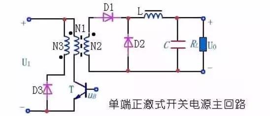
Single-ended: Pulse transformer driven in one direction by a switching device.
Forward excitation: the primary/secondary phase relation of the pulse transformer to ensure that the secondary side of the transformer supplies power to the load when the switch is on and the primary side of the pulse transformer is driven.

The biggest problem of this circuit is that the switch tube T works alternately in the on/off two states. When the switch tube is turned off, the pulse transformer is in the "no-load" state, in which the stored magnetic energy will be accumulated to the next cycle, until the inductor is saturated, so that the switch device burns down. The magnetic flux reset circuit composed of D3 and N3 in the figure provides a channel for discharging excess magnetic energy.
Single-ended flyback
The flyback circuit is opposite to the forward circuit. The primary/secondary phase relationship of the pulse transformer ensures that when the switch is on and the primary side of the pulse transformer is driven, the secondary side of the transformer does not supply power to the load, that is, the primary/secondary side interleaving. The problem of magnetic energy accumulation in pulse transformer is easy to be solved. However, due to leakage inductance in the transformer, voltage spikes will be formed on the primary side, which may break down the switching device. Therefore, a voltage clamp circuit needs to be set to protect the circuit composed of D3 and N3. From the circuit diagram, the flyback type and forward type are very similar, on the surface of the transformer with the same name of the end of the difference, but the working mode of the circuit is different, D3, N3 is also different.

Main advantages: high frequency transformer core utilization rate (compared with single-ended circuit), high supply voltage utilization rate (compared with half bridge circuit described later), high output power, low level of both tube bases, simple drive circuit.
Main disadvantages: low utilization rate of transformer winding, high voltage requirement of switch tube (at least two times of power supply voltage).
The whole bridge
The characteristic of this circuit structure is that four identical switch tubes are connected into a bridge structure to drive the primary side of the pulse transformer.

In the figure, T1 and T4 are a pair, driven by the same set of signals, and both switch on and off at the same time. T2 and T3 are another pair, driven by another set of signals, at the same time on/off. Two pairs of switching tube wheels flow/break, forming positive/negative alternating pulse current in the primary side coil of the transformer.
Main advantages: compared with push-pull structure, the primary side winding is reduced by half, and the voltage resistance of switch tube is reduced by half.
Main disadvantages: the number of switches used is large, and requires good parameter consistency, the driving circuit is complex, and it is difficult to achieve synchronization. This circuit structure is usually used in super high power switching power supply circuits above 1 kW.
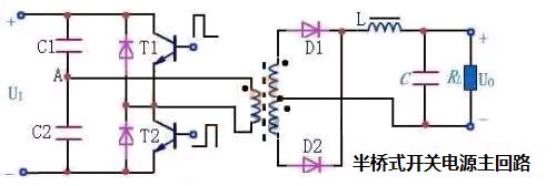
A half bridge type
The structure of the circuit is similar to the full bridge type, except that two switches (T3 and T4) are replaced with two equivalent large capacitors C1 and C2.

Main advantages:
It has a certain ability to resist unbalance and is not very strict with the symmetry of the circuit. Adapt to a large power range, from tens of watts to kilowatts can be; Switch tube voltage requirement is low; The circuit cost is lower than the full bridge circuit.
This circuit is often used in a variety of unregulated output DC converters, such as electronic fluorescent lamp driver circuits.
Share


站LOGO.png)


.jpg)